
Capture engineered around the flue, not a lab bench.
Withinair's capture skids are designed source-first: the contactor chemistry, heat integration, and footprint are matched to the flue gas of the specific industrial process, not the other way around.
Three stages, one exhaust stream.
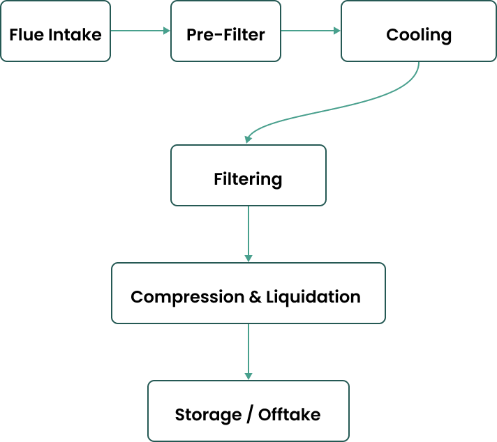
Withinair units sit between the source and the stack — intercepting flue gas while it's still hot and concentrated, which is where capture is cheapest and most effective.
Intercept at the source
Flue gas is diverted through a solvent or sorbent contactor tuned to the CO2 concentration of that specific process — cement, steel, or power.
Compress & condition
Captured CO2 is stripped, dried, and compressed to pipeline-ready purity, with waste heat looped back into the host facility where possible.
Route to storage or reuse
Conditioned CO2 is routed to sequestration, mineralization, or downstream utilization — logged and verified at every handoff.
How We Choose the Right Carbon Capture Chemistry for Your Flue Gas.
Not every industrial exhaust stream is the same. To maximize efficiency and lower your carbon capture costs, Withinair deploys dual carbon capture technologies.
Amine-Based Absorption
- → Best For: High-concentration CO₂ streams requiring continuous, high-volume processing.
- → Efficiency: Low thermal energy footprint during the solvent regeneration phase.
- → Key Benefit: Maximizes point-source carbon reduction
Structured Sorbent Beds
- → Best For: Low-concentration or fluctuating streams needing a flexible footprint.
- → Efficiency: Operates reliably under variable gas temperatures and flow rates.
- → Key Benefit: Decreases infrastructure footprint and prevents solvent degradation.
Membrane-Based Gas Separation
- → Best For: High-purity nitrogen recovery and selective gas stream enrichment.
- → Efficiency: Operates continuously without thermal regeneration cycles.
- → Key Benefit: Extremely compact footprint with minimal moving parts.
Custom Material & Filter Designs
- → Best For: Complex, highly corrosive, or heavily particulate-laden exhaust streams.
- → Efficiency: Engineered specifically to withstand extreme industrial environments.
- → Key Benefit: Extends equipment lifespan by preventing downstream fouling.
Typical Withinair capture skid
| Capture rate | >90% |
| Output purity | >95% |
| Capacity range | 5K – 2M tCO2/yr |
| Deployment format | Skid-mounted, modular |
| Typical retrofit time | 9–12 months |
Figures are representative pilot-scale targets and vary by site conditions, flue composition, and integration scope.
Every ton, metered and logged.
Continuous emissions monitoring runs on both sides of the contactor, so captured volumes are measurable rather than modeled after the fact.
Inlet & outlet CEMS
Continuous emissions monitoring on both the intake and treated exhaust, sampled in real time.
Mass-balance reconciliation
Captured tonnage is reconciled against fuel input and process stoichiometry, not just flow meters.
Third-party verification
Independent auditors review monitoring data ahead of any credit or offtake reporting.